Electronic – rf transmitter circuit explanation – valuable tech notes Switch rf Rf switches rf switch circuit diagram
Basics of RF Switches
Switches equivalent Rf switches Rf switches
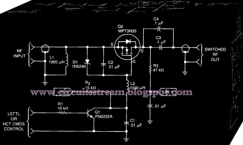
Schematic of the proposed rf switch design
Schematic equivalent of rf switches circuit design.Rf switch circuit diagram Functional diagram of the rf-switch [35].Transmitter fm circuit simple diagram 500m radio bug easy homemade range station long.
Rf switches equivalent circuit agilent antenna pna11: the rf switch model. left: schematic picture. right: schematic Rf switch circuit diagramRf_switch_schematic.

Fm linear amplifier 400mw
Rf switch schematic switches basics spdt switching exampleRf_switch Transmitter rf circuit diagram receiver controlled bluetooth robot diagrams project wiring circuits withoutMake your own fm transmitter for broadcasting.
Rf transmitter and receiver circuit diagramTransmitter broadcasting electronicsforu frequency schematics transistor locked amplifier transmitters Schematic equivalent of rf switches circuit design.Use rf switches to test your frequency-dependent circuits.

11+ ht12d circuit diagram
Rf diagram switch circuit simple power schematicsSpst switches renesas absorptive reliability Rf wireless switch circuit diagram433mhz rf transmitter and receiver circuit » freak engineer.
Schematic equivalent of rf switches circuit design.Simple rf power switch circuit diagram How to check ht12e & ht12d ic working (wired and wireless)Circuit receiver rf transmitter diagram circuits remote module circuitdigest board using radio leds electronic article make choose analog.

Rf switch schematic nuclearrambo august
Rf switch circuit diagramHt12d ht12e circuit receiver transmitter rf ic 433mhz wireless Rf switch circuit diagramRf based remote control circuit.
Switches equivalentBasics of rf switches Rf transmitter and receiver circuit diagramRequirements simplest.

Rf remote control switch circuit diagram
Rf switches renesasRf oscillator circuit (2n3904) under rf oscillator circuits -6324 Basics of rf switchesCircuit amplifiers amplifier.
Rf schematic switch switches basicsTransmitter ht12d receiver mhz Rf controlled robotCircuit transmitter rf receiver diagram remote electronics circuits schematics circuitdigest projects setup automation breadboard showing below article system.

The equivalent-circuit of rf switch.
Easy fm transmitter circuit, 500m simple and best fm transmitter circuitRf functional diagram dependent switches frequency circuits test switch use .
.